
Description of a Processor
In this article, we will describe the processor of a
hypothetical computer which we will call HYPCOM. The reason why we
use a hypothetical computer is that it is easy to explain fundamental ideas
with a simple model. Real commercial computers are too complex to explain basic
ideas to a beginner. The processor of HYPCOM has an
accumulator register (ACC). A register is an interconnected set of memory
cells, each storing a bit. The other registers in the processor are an
instruction register (IR) and a program counter (PC). The instruction register
is used to temporarily store the instruction being executed. It consists of two
parts: an operation code part and an address part. The PC register stores the
address of the next instruction to be executed. The block diagram of HYPCOM processor is shown in Figure
below.
{tocify} $title= {Table
of Contents}
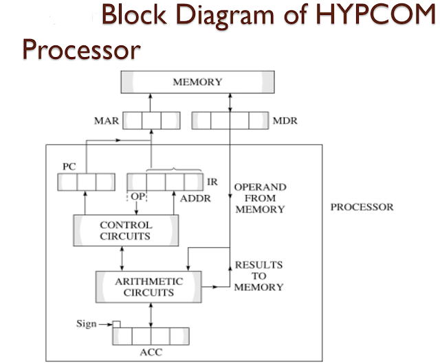 |
Figure of Logical
Structure of HYPCOM Processor |
The other
specifications of HYPCOM are:
i. It has a 4K word addressable memory.
ii. A word of HYPCOM is 16 bits long.
iii. A word of HYPCOM stores either an instruction or data to be processed.
iv. It has 15 operation codes.
v. The instructions are single-address instructions. Four bits are needed to represent 15 operation codes. Twelve bits are needed to address a 4K memory. An instruction is thus 16 bits long.
vi. It has an input unit which is used to feed both instructions and data. A 16-bit word is read via the input unit and stored in the memory when a READ operation code is executed by a processor.
vii. It has a printer as its output unit which is used to output a 16 – bit word from the memory when a PRINT operation code is executed by the processor.
The operation codes of HYPCOM and what each of them does are given
following Table. The logical structure of HYPCOM
is shown in following figure below:


 |
Operation Mode of Hypcom Computer and Their meaningLogical Structure of a Processor |

The operation codes may be grouped as follows:
1. Data movement operation codes
CLA, STO
2. Arithmetic operation codes
ADD, SUB, MUL, DIV
3. Control operation codes
JMP, JNE, JZE, HLT
4. Input/output operation codes
READ, PRINT
5. Logical operation codes
SHR, COM, EOR
The data movement group moves data from the memory to the accumulator and from the accumulator to the memory. The arithmetic group does addition, subtraction, multiplication and division.
The result of an arithmetic operation is left in the accumulator and must not exceed the capacity of the accumulator. The control group is intended to implement decision boxes in flowcharts. Normal sequential execution of instructions is altered when jump instructions are operation on characters. The exclusive-or (EOR) operation is particularly useful to examine whether the contents of two words in memory are identical. Below Table defines the exclusive-or operation between bits. It is seen that if the exclusive-or of corresponding bits of words gives all zeros, then the words are identical.
 |
Table of Exclusive-or operator |